Induction Heating Templates tutorial
When you need to simulate a 2D axial symmetric induction heating case with billet and coil of standard, regular shape, it is convenient to use Induction Heating Templates.
In this tutorial you will learn how to set up and use the Induction Heating Templates for 2D axial symmetric simulation of a cylindrical rod with a rectangular profile coil and a flux concentrator around it. We will create the geometry by choosing one of the available templates for each domain, define the mesh quality, enter the specific values and boundary conditions in the physics setup and in the end evaluate the results using our post-processor.
Induction Heating Template is an easy and fast way to set up and calculate induction heating cases for standard geometries. In the next pages an induction heating example of an AISI 1020 workpiece at 15 kHz and 2 kA with radiation and convection boundary conditions and FLUXTROL A concentrator is presented.
Watch tutorial video on YouTube
Download the application files:
Induction Heating Templates tutorial.pdf
Simulation_tutorial_2D_templates.zip
1. Open pre-processor
To enter geometry templates, in CENOS home window click Template.
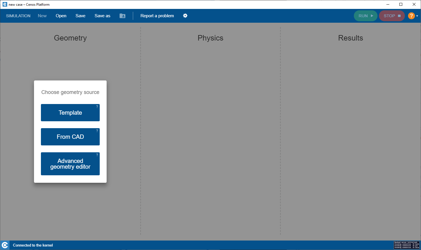
Template automatically defines the non-critical parts of the simulation setup and offers new users a preset simulation physical and geometrical values, so you only need to change the parameters that are already there.
2. Create Geometry
2.1 Choose units and mesh
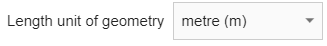
You can define case units in lower left corner of Create Geometry screen. For this tutorial, choose meters as case units.
If you want to change mesh density, click SHOW MESH OPTIONS.

Then choose from Mesh density dropdown.
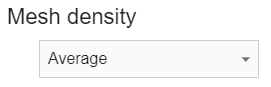
IMPORTANT: When using templates, mesh is generated automatically before the start of the calculation. With Mesh density you define how fine or coarse the mesh will be.
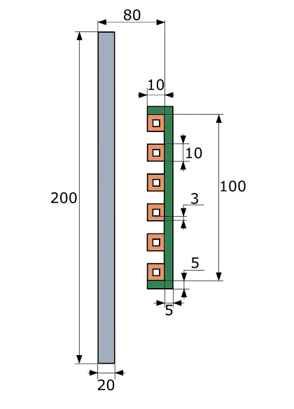
2.2 Set the workpiece geometry
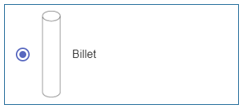
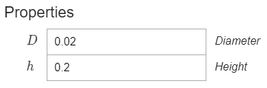
Switch to the WORKPIECE domain. Select Billet for Shape.
Under Properties enter 0.02 for Diameter and 0.2 for Height.
2.3 Set the inductor geometry
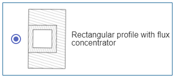
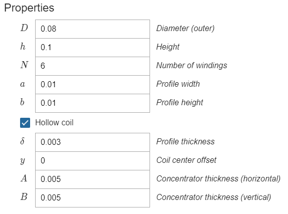
Switch to the INDUCTOR domain. Select Rectangular profile with flux concentrator for Shape.
Under Properties make sure that the Hollow coil box is checked and enter the values for the coil and concentrator as follows:
When the geometry is set, click Go to PHYSICS in the upper right corner of the window.
3. Define physics and boundary conditions
IMPORTANT: Part of the window is painted grey meaning that every setting in the grey area is pre-set for this specific template, leaving only the core settings to your mind.
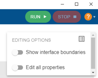
If you want to edit settings in the grey area, enable Edit all properties.
3.1 Simulation control
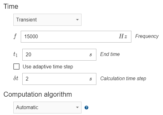
In the SIMULATION CONTROL window you can access and define global simulation parameters such as frequency, calculation time, time step, computational algorithms and many more.
Define the simulation as Transient with 15 kHz frequency, 20 s End time and 2 s time step.
3.2 Workpiece definition
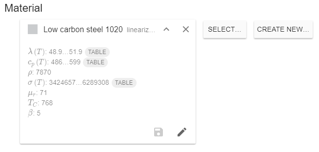
Switch to WORKPIECE in Domain bar. For Material click SELECT… and choose Low carbon steel 1020 linearized (H=100000A/m), %% t^{\circ} %% depend.
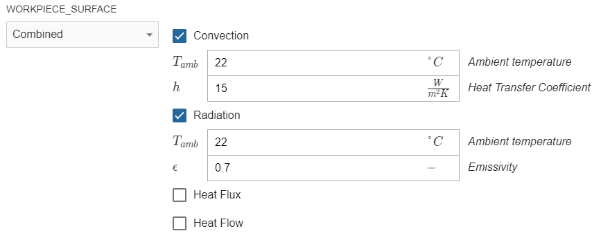
Under THERMAL ANALYSIS choose Combined for WORKPIECE_SURFACE – check the Convection and Radiation boxes and enter 15 for Heat Transfer Coefficient and 0.7 for Emissivity.
3.3 Coil definition
Switch to WINDING_0.. in Domain bar. Enter 2000 A for Current (Amplitude).
3.4 Concentrator definition
Switch to CONCENTRATOR in Domain bar. For Material select Flux concentrator FLUXTROL A.
Physical definition for the air domain is set fully automatically, so after you define concentrator and conductor domains, click RUN in the right upper corner of the window.
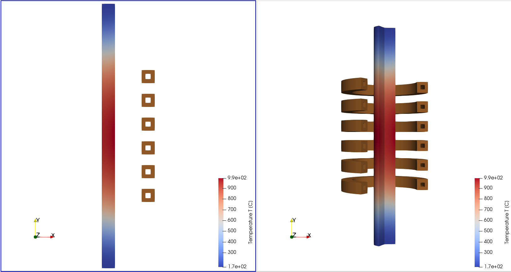
4. Evaluate results
In the end of the calculation the post-processing tool ParaView will automatically open with a pre-set temperature state, and you will be able to see the temperature field distribution in the workpiece in the last time step.
Results can be further manipulated by using ParaView filters - find out more in CENOS advanced post-processing article.
This concludes our Induction Heating Template tutorial. For any recommendations or questions contact our support.