Create simulation with From CAD
You can import premade CAD files and prepare geometry for simulation directly into CENOS.
Generate air box and mesh automatically, and set up simulation without the need for manual geometry or mesh editing.
Select geometry building approach
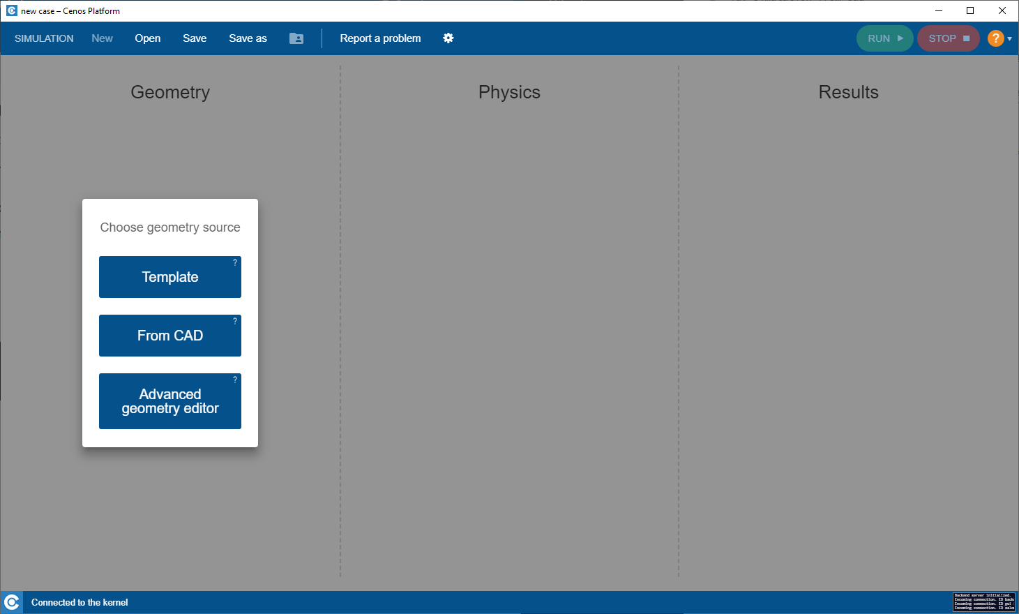
To create geometry from premade CAD, in CENOS home window click From CAD.
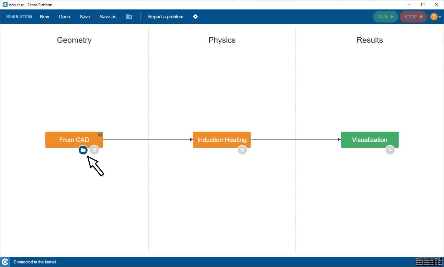
Click on the Folder icon to select and import CAD files.
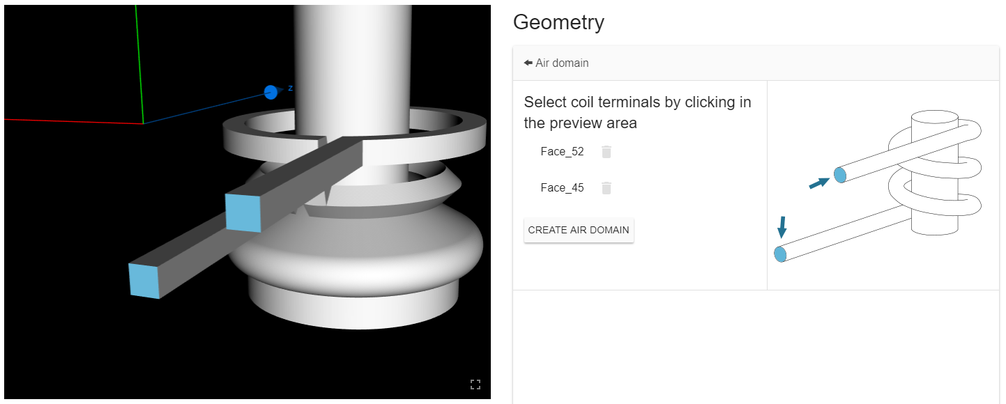
Create Air Box
Create air box automatically.
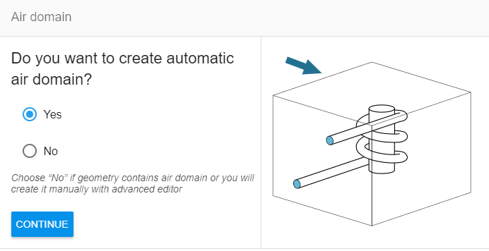
Select inductor terminals as references for air box size.
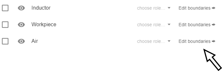
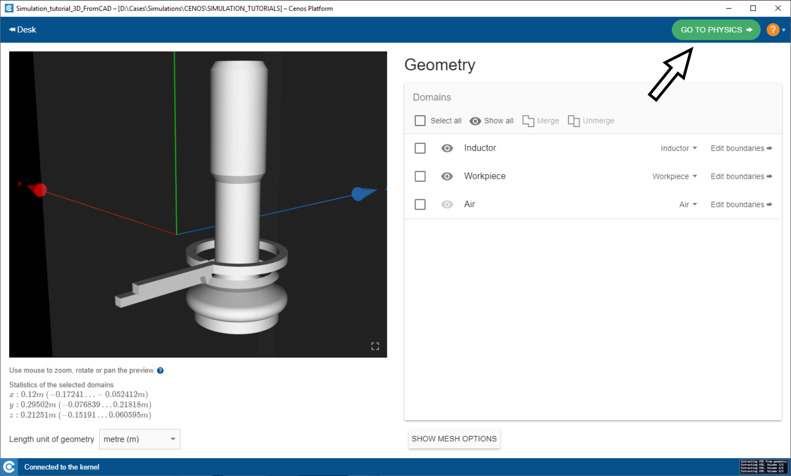
Prepare volumes
IMPORTANT: For easier volume and surface selection and preparation, From CAD incorporates multiple useful tools.

Select all - Selects all volumes or boundaries available for selection.
Show all - Turn object visibility on or off.
Merge - Merge or group multiple volumes or surfaces into one.
Unmerge - Split previously merged or grouped objects into their initial state.
Group and rename volume domains as needed.

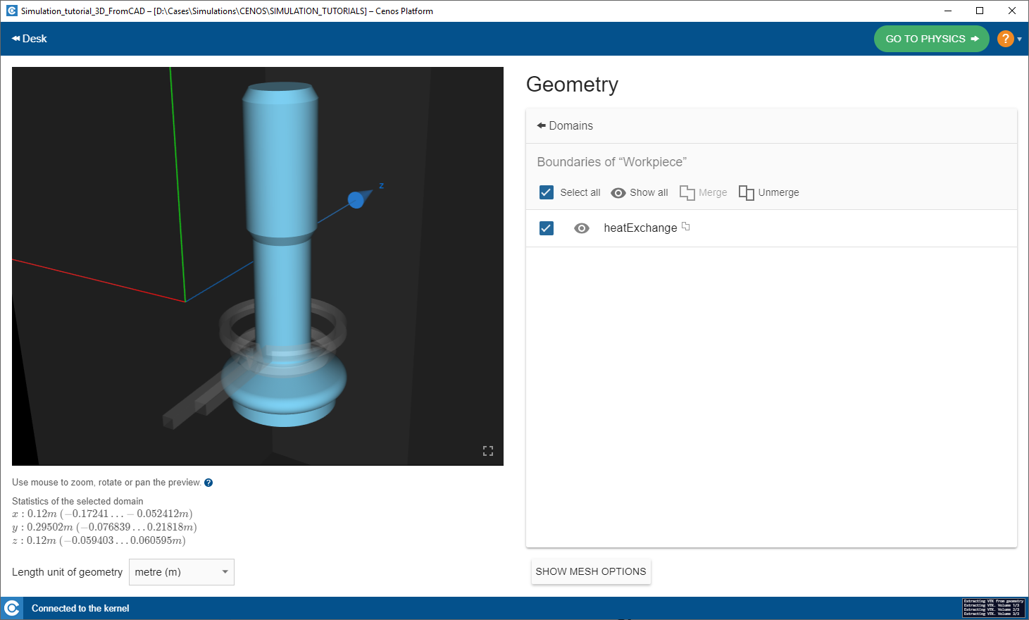
Prepare boundaries
Click Edit boundaries to enter boundary surface editor.
Merge and rename boundaries for heat exchange and electromagnetic definitions.
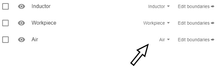
Choose role
To ease physics definitions, select the role of each volume here.
After geometry has been prepared, click GO TO PHYSICS to enter physics setup.
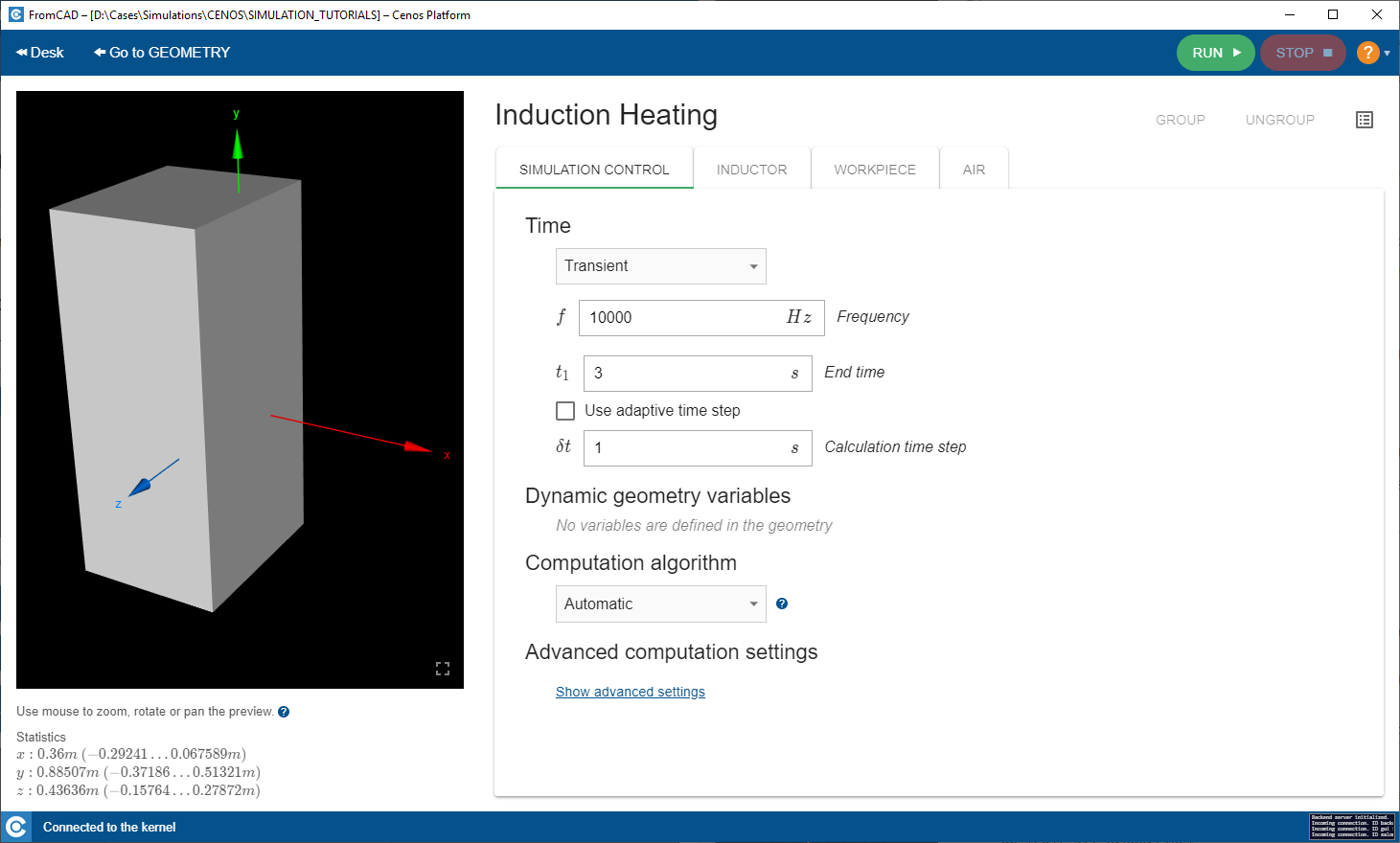
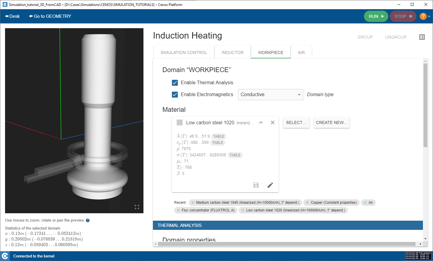
Define simulation parameters
Enter physical parameters
In SIMULATION CONTROL window define global parameters such as frequency, calculation time etc.
In SIMULATION DOMAIN windows such as WORKPIECE define the physical parameters of each domain such as material, heat exchange, current etc.
Post-processing
In the end of the calculation the post-processing tool ParaView will automatically open with a pre-set temperature state, and you will be able to see the temperature field distribution in the workpiece in the last time step.
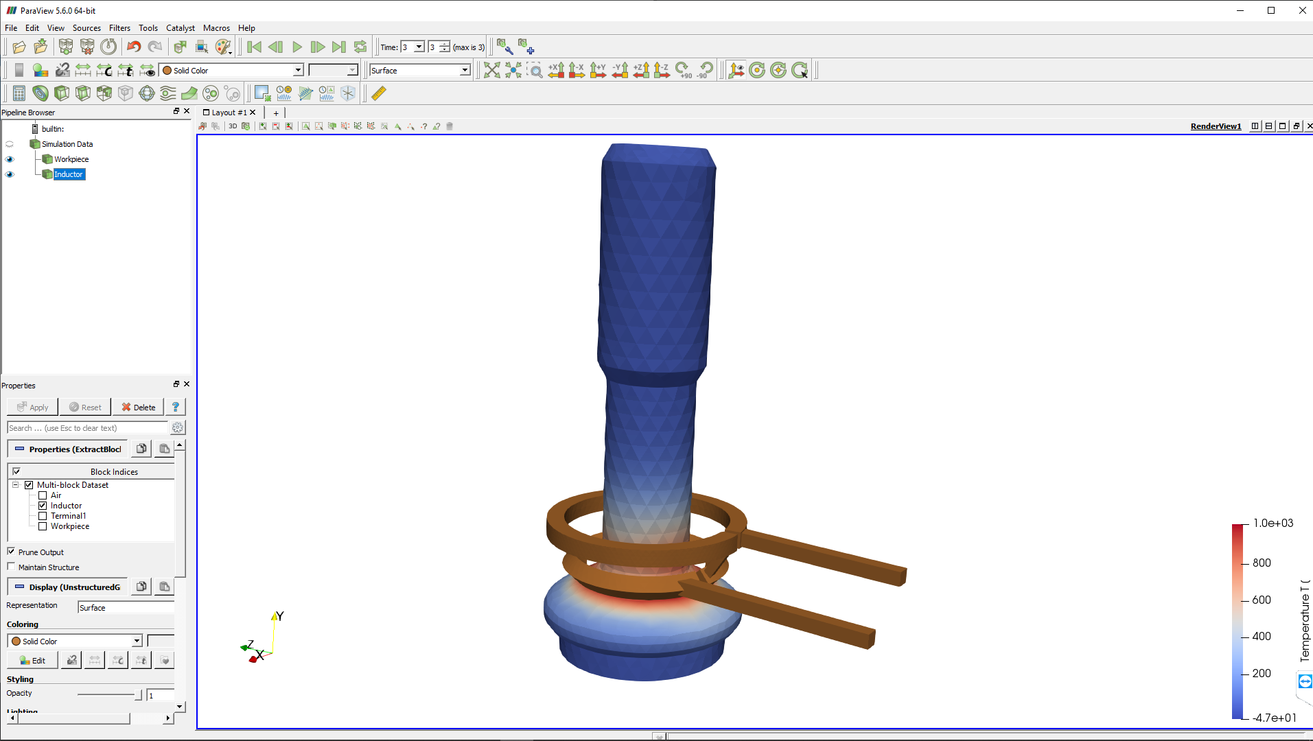
To learn more about result manipulations, visit our post-processing article.
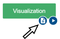
Integral values
For integral values such as apparent power, induced heat and complex voltage you can use the .csv file, which comes along with the visual results. You can access it through Note button next to the Visualization block Play button.