CENOS Documentation

CENOS Documentation

  • CENOS Home
  • Simulation Examples
  • Webinars

›Explained

Getting Started

  • CENOS overview
  • Templates
  • Using CAD files
  • Tips and Tricks

Tutorials

  • Induction Heating Templates
  • 2D Stepped Workpiece
  • 2D Scanning of Transmission Shaft
  • 3D Single Shot
  • 3D Spur Gear Hardening

FAQ

  • Frequently asked questions

How To

  • Creating 3D CAD models
  • Fluxtrol thermal calculation
  • From CAD
  • Geometry parameterization
  • How to make good CAD
  • How to run multiple simulations
  • Large rotating workpieces
  • Result evaluation
  • Scanning applications
  • Stranded Coil/Litz wire
  • Field expressions
  • Mesh : Overview
  • Mesh : Extrusion
  • Estimate effective μ
  • Movement : Scanning
  • Movement : Rotation
  • Phase change calculation

Explained

  • Algorithms
  • Mesh quality : Aspect ratio
  • Mesh quality : Taper
  • Boundary conditions
  • Geometry simplification
  • Heat Exchange
  • Material properties
  • Mesh troubleshoot
  • Role of air domain size
  • Symmetry Boundary Conditions
  • Thermal shock
  • Power control
  • Time step

Release Notes

  • v3.x
  • v2.x
  • v2018.x

Thermal shock

When initially hot body is suddenly cooled or a cold body is suddenly heated through the surface, a steep variations in temperature called thermal shocks may appear. An example of this might be heating with radiative heaters with known power or with resistive heaters mounted directly on the wall. In these cases one should use Heat flux W/m2W/m^2W/m2 or Heat flow WWW boundary condition.

Thermal shocks have short-term effect and their effect vanishes when the temperature profile is developed. But proper resolution of these effects puts additional constraints on the time step and mesh resolution in FEM analysis:

Δt=ρcλΔx6 \Delta t = \frac{\rho c}{\lambda} \frac{\Delta x}{6} Δt=λρc​6Δx​

Here Δt\Delta tΔt is the time step, Δx\Delta xΔx is the mesh size. The coefficient 6 is empyrical, and varies in different literature sources.

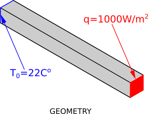
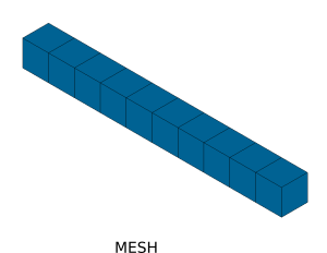
To illustrate the problem, let's consider 1D example (in CENOS it is made as 3D case with 1 element thickness in Y and Z directions and N divisions in X direction):

The bar has properties λ=50W/mK\lambda = 50 W/mKλ=50W/mK, ρ=1000kg/m3\rho = 1000 kg/m^3ρ=1000kg/m3, c=500J/kgKc = 500 J/kg Kc=500J/kgK. The length is 1 m, initial temperature and temperature on the left side T0=22CT_0 = 22 CT0​=22C, the heat flux q=1000W/m2q = 1000 W/m^2q=1000W/m2.

Let's consider the mesh with N = 5, so Δx=0.2m\Delta x = 0.2 mΔx=0.2m. This leads to the critical value of time step Δt=400s\Delta t = 400 sΔt=400s.

Bar Geometry

Bar Mesh

The temperature distribution in the bar after 50 seconds obtained with Δt=5\Delta t = 5 Δt=5 and different mesh sizes are shown in the figure below:

thermalShock

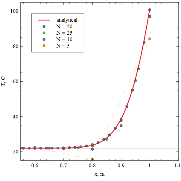
This figure shows that for the mesh with N=5 N=5N=5 (Δx=0.2)(\Delta x = 0.2)(Δx=0.2) unphysical temperature appears at the value x=0.8x=0.8x=0.8. Since initial condition and boundary condition on one end is 22 C, temeperature should never be below this value. In other words, the temperature and the mesh size are linked and cannot be chosen totally independently.

Here are few articles for further reading:

https://support.ansys.com/staticassets/ANSYS/staticassets/resourcelibrary/confpaper/2002-Int-ANSYS-Conf-91.PDF

https://hal-mines-paristech.archives-ouvertes.fr/hal-00576032/document

← PreviousNext →
Copyright © 2021 CENOSRelease Notes