Creating 3D geometry with FreeCAD
FreeCAD is a completely free, open source CAD modeler which you can use to create 2D or 3D geometry for your simulations.
With the help of this short guide of FreeCAD, hopefully, you will be able to quickly create advanced geometry for your simulation cases.
FreeCAD download: https://www.freecadweb.org/
What you can create with FreeCAD
The main purpose of FreeCAD is to create a STEP file for CENOS. You can use any CAD software to prepare STEP files but FreeCAD will allow you to create 3D geometry from scratch, or use your 2D cad files as a base. FreeCAD has most of the features of ther CAD programs, such as most of the modeling tools and parametric design, all of which make modelling quick and easy, saving you time and money.
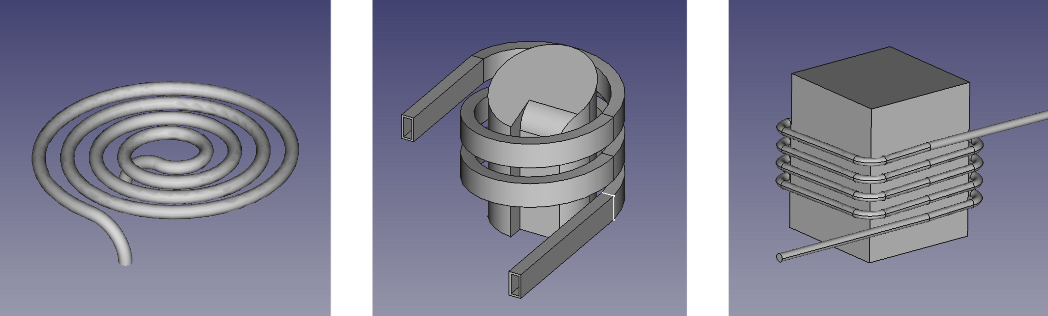
With FreeCAD will be able to create much more complex geometries than covered in this guide. But here are a few examples:
Work environment and controls
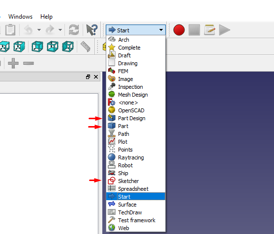
FreeCAD is a very universal piece of software, and has many workbenches which are different work environments with different tools for various applications, but we will mainly use Sketcher, Part and Part Design.
Camera controls:
| Select | Pan | Zoom | Rotate 1 | rotate 2 |
|---|---|---|---|---|
 |  |  |  | |
 |  |  |  |  |
| Press the left mouse button over an object you want to select. Hold Ctrl for selecting multiple | Hold the middle mouse button, then move the pointer around. | Use the mouse wheel to zoom in and out. Clicking the middle mouse button re-centers the view on the location of the cursor. | Hold the middle mouse button, then press and hold the left mouse button, then move the pointer. | (Same as rotate 1) Hold the middle mouse button, then press and hold the right mouse button, then move the pointer. |
Importing 2D drawings
FreeCAD can import the following formats: STEP, IGES, OBJ, STL, DXF, SVG, STL, DAE, IFC or OFF, NASTRAN, VRML
If you wish to import, for example, a 2D .DXF drawing for further modification, there will be a few steps:
- Import DXF file from File → import
- Delete unnecessary elements before the next steps
- Convert the lines to a sketch by going into Draft workbench, then Draft → Draft to sketch.
- Merge the created sketches into one by going into Sketcher workbench, then Sketch → merge sketch.
Raw imported DXF file:
DXF converted into sketches:
Creating 2D sketches
2D sketches can be used solely for 2D simulations or as a basis for further 3d operations such as extrude, revolve or sweep.
These sketches will be created in the Sketcher workbench. It should be straight-forward creating them, but here are some tips to help you along:
- Left click-hold and drag lines or points around, to see missing constraints.
- If you can't constrain or position an object, use Construction lines

- If you want to create a sketch on a surface of an object, select the face and then create sketch.
- When working on a face sketch, use Create edge linked to external geometry

- To move a sketch, for example, on the end of a coil, use the position parameters in properties
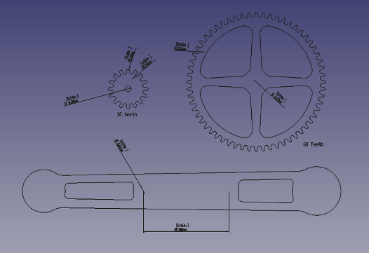
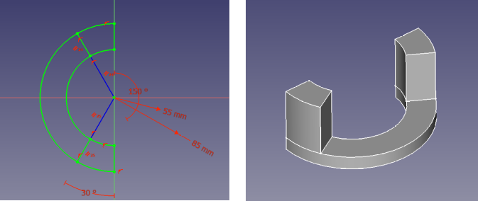
Example of a sketch created for extruding:
3D Geometry creation
Geometry creation
3D modelling in FreeCAD can be done in the Part workbench.
 A primitive object can be created using the yellow primitive solids, but usually the most efficient way to create the desired object is to start from a sketch. In most cases you can extrude, revolve or sweep a sketch.
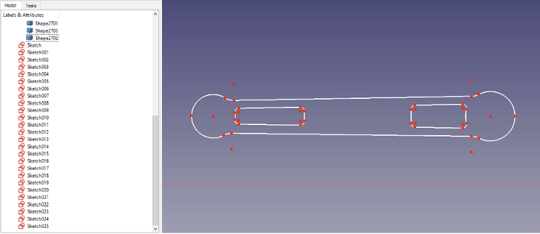
Example of a model created with extrusions, and revolve
FreeCAD is a parametric modeler like many other CAD programs, so you can change the parameters of an operation in the properties on the left or you can edit the base sketch afterwards.
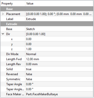
Example properties of an extrusion:
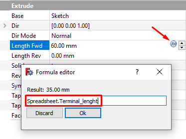
Geometry parameterization
In FreeCAD you can create a spreadsheet to parametrically determine An objects properties. This works both with objects such as extrude, or sketch dimensions.
- Create a spreadsheet in the spreadsheet workbench
- Create a variable name for the Property in column A
- Write the dimension, for example, as = 35mm
- Right click the dimension cell, go to Properties → Alias and give it an alias
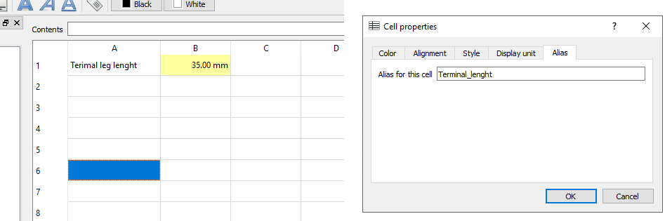
- Close the spread sheet
- Go the property you want to apply the parameter to
- Click on the little expression button and write Spreadsheet.alias, for example, Spreadsheet.Terminal_lenght
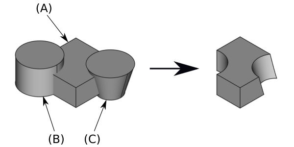
Boolean operations
Boolean is a very powerful tool used for combining or splitting objects that comes in many types: Union, Cut, Difference and multiple others.

To use boolean you must first select the active (A) body, and then the tool body (B, C)
Creating coil inductors (Sweeping)
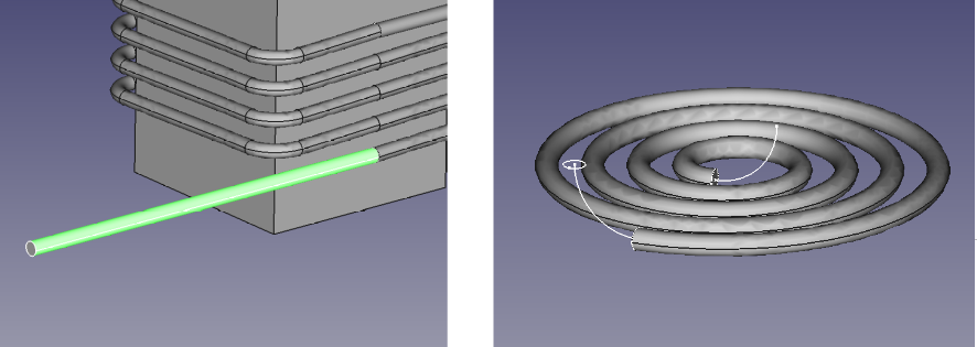
If you need to create a coil inductor, you will probabaly use the Sweep tool, which can be found in the Part workbench. Sweeping requires a profile and a path.
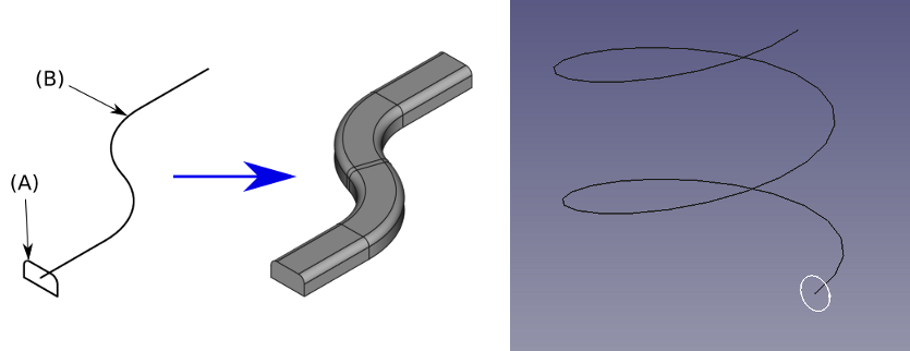
- Create a helix or spiral to the desired dimensions with Create parameterized primitive
 in part workbench
 - Create a sketch of the desired profile and position it at the beginning of the helix. You can change the sketch position in it's properties.
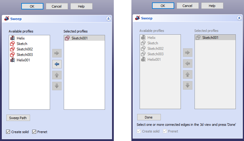
- Open the sweep tool

- Select the sketch which will be your profile (A) and check create solid and frenet if the profile is not a circle.
- Click Sweep Path and select all of the path lines (B) in the 3D viewfinder holding Ctrl.
- Then click done and click OK.
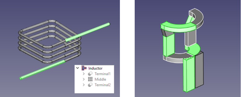
Creating terminals
Once you have the coil, it will need some kind of terminals Sometimes you cannot sweep along multiple connected paths (usually with helix or spiral), so there is a simply workaround. Just sketch additional lines and sweep those separately, or extrude the ends off a face sketch for straight terminals as shown here:
Limitations:
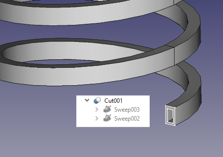
The profile of the sweep mush be a closed line, meaning you can't create a hollow inductor. This is easily solved by doing two sweeps - one with the outer shape and one with the inner. Then you just use a boolean cut to make it hollow:
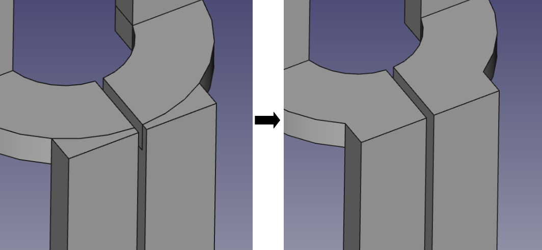
Fusing parts into one solid
For the meshing and subsequently your simulation to run without errors, each of the domains must be a single solid. If your inductor, for example, is made up of multiple pieces, as shown here, you must fuse them into a single solid. This is done very easily with a simple connect objects operation.
IMPORTANT: Do not use boolean join/union to fuse parts. It will not work, and can leave unwanted faces between parts. This will result in a compound solid which will not mesh properly.
To further clean up the objects, you can use Create refine shape feature under the OpenSCAD workbench.
There are a few more requirements for a successful simulation, and it is highly suggested to read up on how to create good CAD model
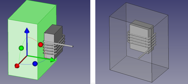
Air domain
For full 3D simulations you don't necessarily have to create the air domain, CENOS can generate it automatically. But if you are using symetry you need to create it manualy.
- Create cube solid
- Enter the necessary dimensions under properties
- Double click the cube in the model tree view, this will enable transform mode, position the cube.
- Use boolean operations as needed in your case
Exporting to CENOS
Exporting files in FreeCAD is dead simple. Just select the body or multiple bodies you wish to export, go to File → Export and select STEP file. You can export all of your bodies in a single or seperate STEP files, CENOS can import them either way. However it is suggested to export them separately, so if there is a problem with one of the components, it is easier to troubleshoot.
If exporting a single sketch for a 2D simulation, make sure to exit sketch mode, otherwise it will not work.
Further learning and help
FreeCAD has a wiki page which contains extensive information on all of its features: https://www.freecadweb.org/wiki/Main_Page
Aswell as some tutorials for modellling parts:
https://www.freecadweb.org/wiki/Tutorials
There is also a FreeCAD manual, which is a more linear way of learning the program: https://www.freecadweb.org/wiki/Manual:Introduction
If you're stuck on a certain problem, there is also an acive forum with pleanty of knowledgeable users willing to help:
https://forum.freecadweb.org/