From CAD function
From CAD is a geometry creation approach in CENOS, which allows user to import CAD file and prepare it for simulation without manual geometry modifications or mesh creation, as the mesh is being generated automatically!
In this article we will learn how to use From CAD geometry preparation approach, as the rest of the simulation workflow (physical setup and results) remains the same.
When to use From CAD function?
From CAD is useful for geometries which have been made in separate CAD softwares following the rules for a good CAD.
Simply import CAD of your inductor, workpiece etc., define simulation domains, boundaries and physics, and run the simulation!
How to use From CAD?
The basic workflow for this geometry creation approach consists of four parts:
CAD creation - in CAD software create your geometrical model for inductor, workpiece and flux concentrators and save them in one or separate STEP files.
Import CAD - use From CAD function to import your CAD files into CENOS.
Domain definition - Group and rename different volumes to define simulation domains such as workpiece, inductor and air.
Boundary definition - Define boundary surfaces for each domain.

Create CAD
In a separate CAD software build the geometry for the simulation. In one or more STEP files prepare workpiece, inductor, concentrator geometries.
IMPORTANT: For full geometries air domain can be created automatically in CENOS, but for slices and other symmetry cases you need to create and import air domain along with the rest of geometry.
Import model
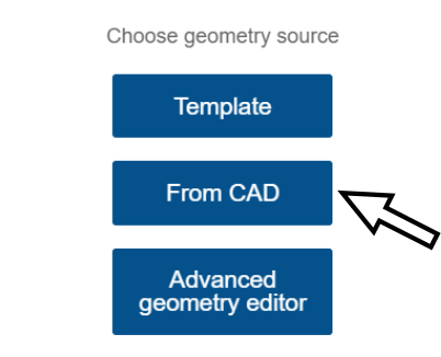
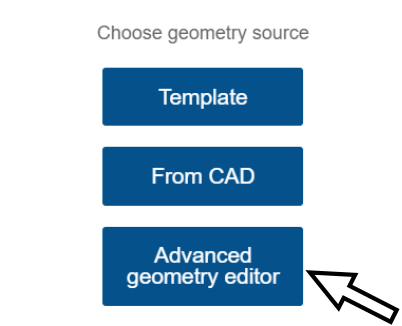
In CENOS home window from Choose geometry source select From CAD approach.
Click the File folder icon and select one or more CAD files to import.

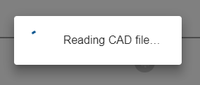
A dialogue window will open. Find and select your CAD files and click Open. Wait while geometry loads.
Create air domain
When geometry is loaded, you need to specify if you want to automatically create air domain.
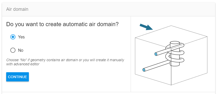
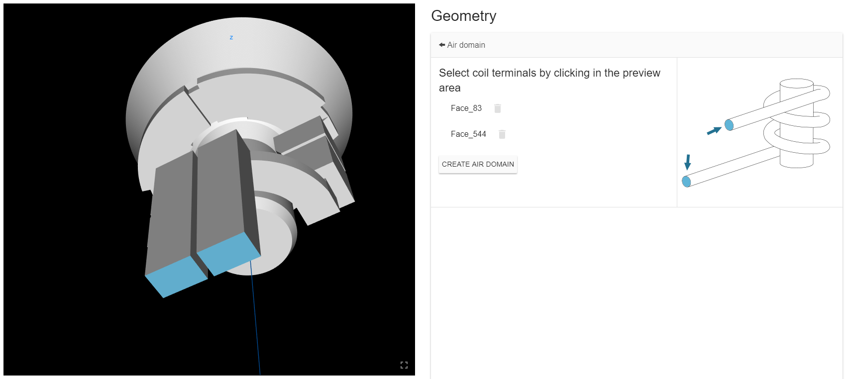
For full geometries you can create air domain by selecting inductor terminal ports as reference.
For symmetry geometries (slices, halfs etc.) you need to create ar domain separately and import it together with the rest of the geometry.
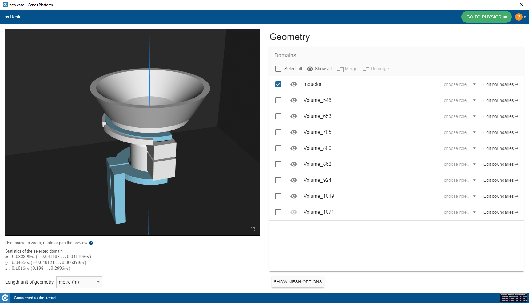
Define simulation domains
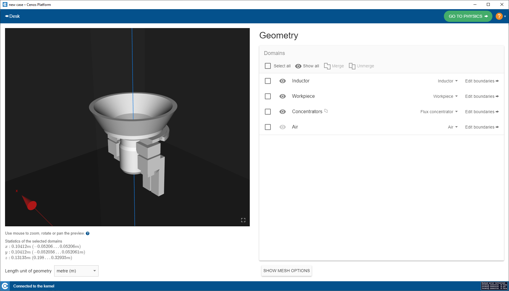
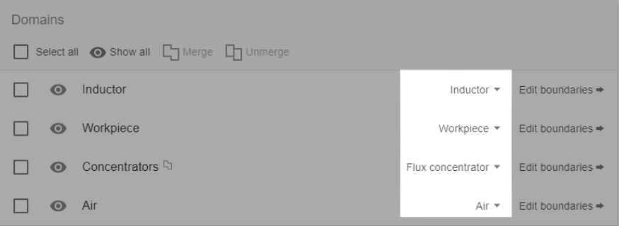
Geometry setup window consists of an interactive preview window and object browser (left and right part of the window respectively). Select domains from preview window or object browser, rename them and group (Merge) if necessary, to properly define simulation domains.
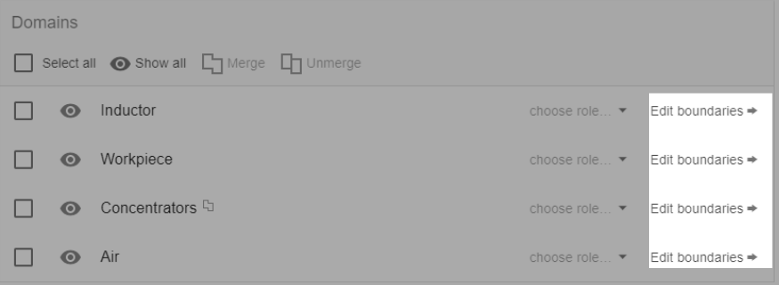
Select volume which, for example, conforms with inductor domain, and rename it Inductor. This volume will later appear in the physics setup as Inductor domain, and you will be able to define physical properties for this domain. In the same way define Workpiece , Air and other domains.
You can group different volumes by selecting them and clicking Merge button in the Object Browser.
To change geometry units, select the appropriate unit from the Base unit dropdown in the lower left corner of the geometry window.
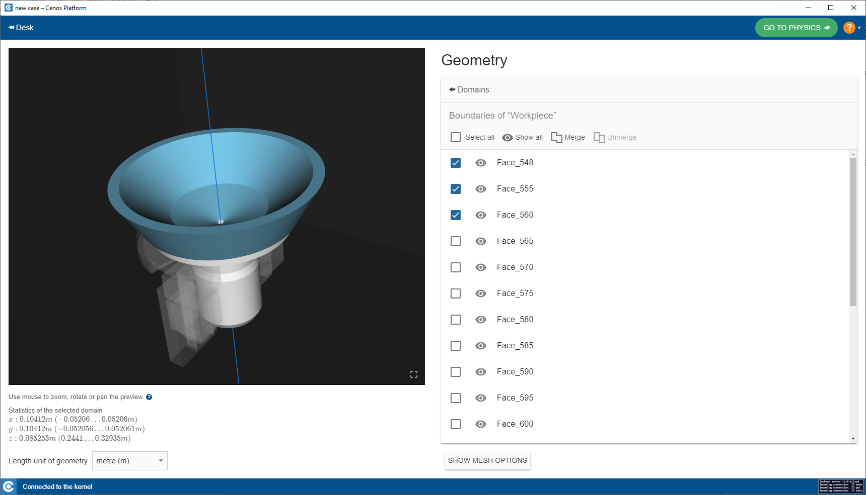
Define boundary surfaces
In the Object Browser, when every domain has been defined, click BOUNDARIES to enter boundary surface selection for each volume domain.
In the same way as with domains before, select the surfaces of each volume domain, group and name them to define boundary surfaces, which will later appear in the physical setup part and you will be able to define Boundary Conditions for these surfaces.
Choose role
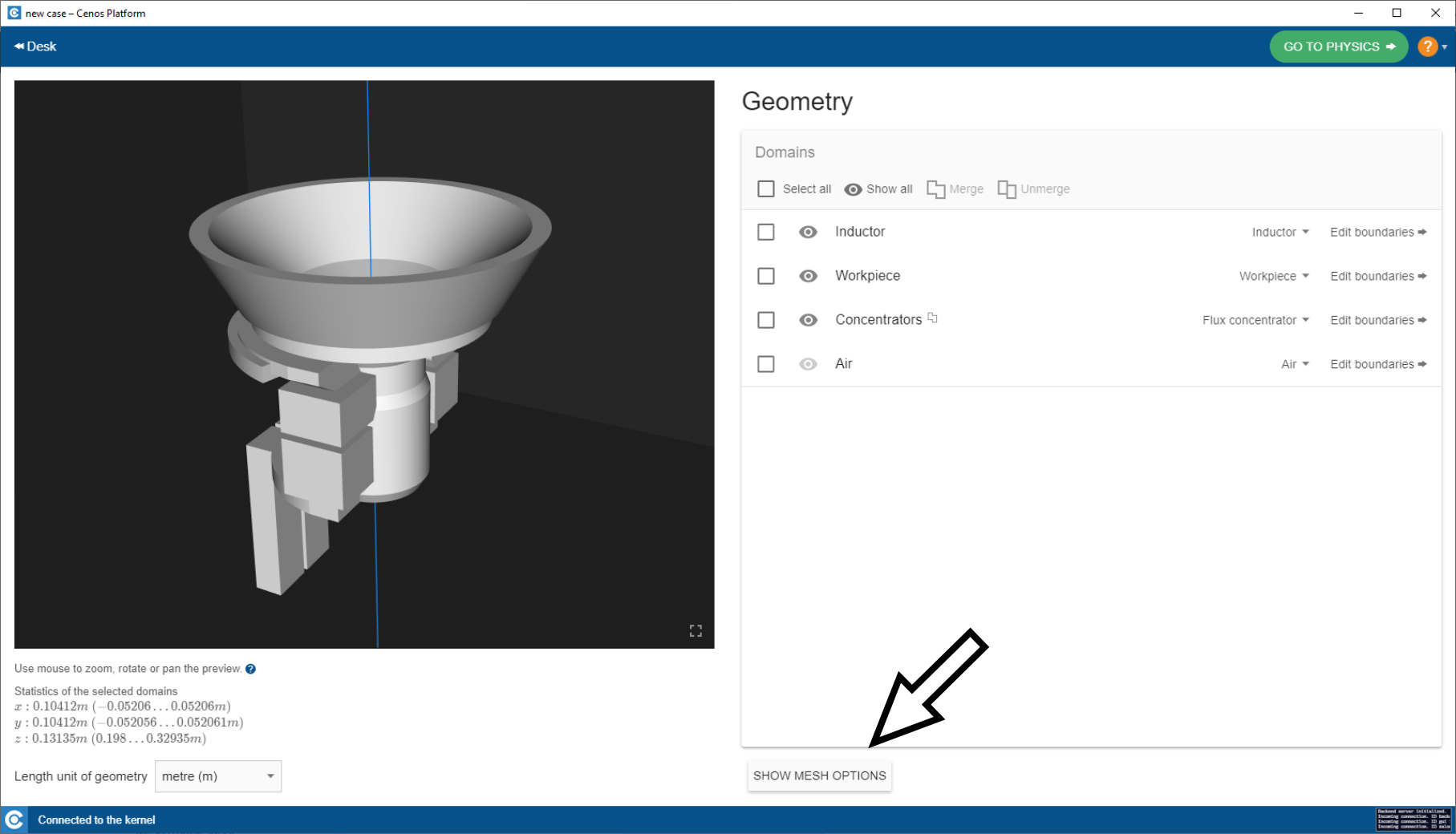
In geometry window you can predefine the role of each domain. This will help in physics setup, as defining the role of domain will automatically choose the simulation analysis (Thermal, EM or both) and Domain type for specific volume domain.
When geometry has been prepared, click GO TO PHYSICS to define physical part of the simulation.
Limitations
Even though From CAD is a very easy to use geometry preparation approach, it still has its limitations and requirements to follow.
CAD files
If you want to simulate symmetry cases such as slices, halfs etc., you will need to create air domain separately and import it along with the rest of geometry, as CREATE AIR DOMAIN works only for full geometries.
| Geometry type : | Air creation : |
|---|---|
| Full geometry | Automatically in CENOS |
| Symmetry (slice, half etc.) | Separately |
Scanning
From CAD approach does not support scanning yet, so, if you want to simulate scanning, create the simulation through Advanced geometry editor.
Automatic meshing
From CAD approach meshes the geometry automatically, using automatic meshing algorithms. If the geometry is faulty or too complex for automatic meshing algorithms to handle and the mesh crashes, you need to build the mesh manually.
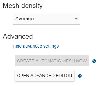
To manually edit mesh, click SHOW MESH OPTIONS.
In Mesh options window click OPEN ADVANCED EDITOR. This will open Salome, where you can manually edit and fix the mesh.