Tips and Tricks for new users
As a new CENOS user, the information you need to know about simulations, their setup, troubleshoot and many other things are really overwhelming. Most of these things you will learn as you progress through tutorials and your personal projects, but some are not as straightforward.
In this article we will look at the most common mistakes for the first time users, which you should consider if you want to create a successful simulation.
NOTE: Even though these tips are useful to avoid unnecessary headaches about why the simulation isn't working, we advise to schedule a meeting/training with our engineers to talk about simulation setup in detail and to answer any questions or confusion you might have.
Watch introduction VIDEO about CENOS workings:

Because different mistakes are made at different parts of simulation setup, we will divide the tips into three categories:
- Geometry
- Mesh
- Physics
Geometry
Every simulation starts with a geometry. If you have not simplified the geometry, fixed CAD quality or made sure the positioning is correct, you will have a hard time getting the simulation to work.
CAD quality
Before you create a simulation, make sure that your CAD file is simulation-friendly. Learn more about how to make good CAD for induction heating simulation.
Take away every small hole, fillet and other details which are not relevant for the simulation, but will make meshing harder and increase the calculation time if you do not take them out. Avoid building your geometry from smaller volumes, and always fuse them together before importing it in CENOS.
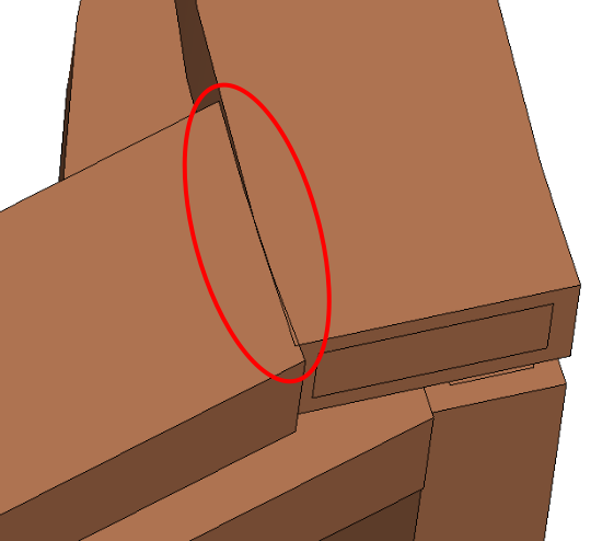
Resolve any overlappings and gaps, and make sure your geometry is continuous.
Symmetry
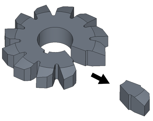
Use symmetry of your geometry and simulate only part of the full geometry to decrease calculation time. To simulate symmetry, use symmetry boundary conditions available in CENOS.
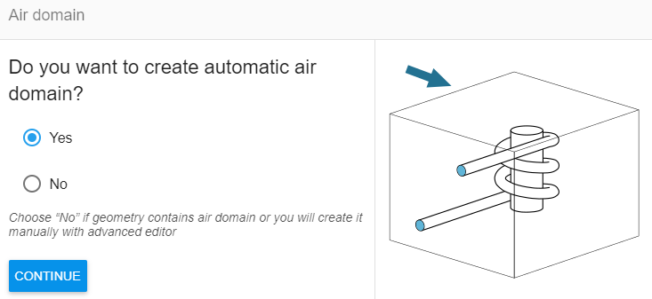
Air box size
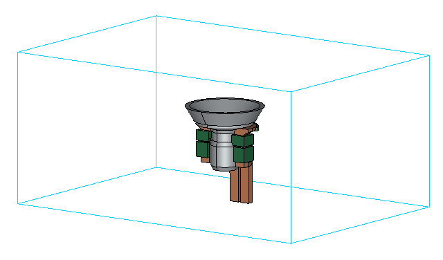
Air box is used for EM field calculation, and air box size can directly affect simulation results.
Do not create the air box too small, otherwise the results could be incorrect. A good rule is to make the air domain around 3 times larger than the induction system in it in every direction.
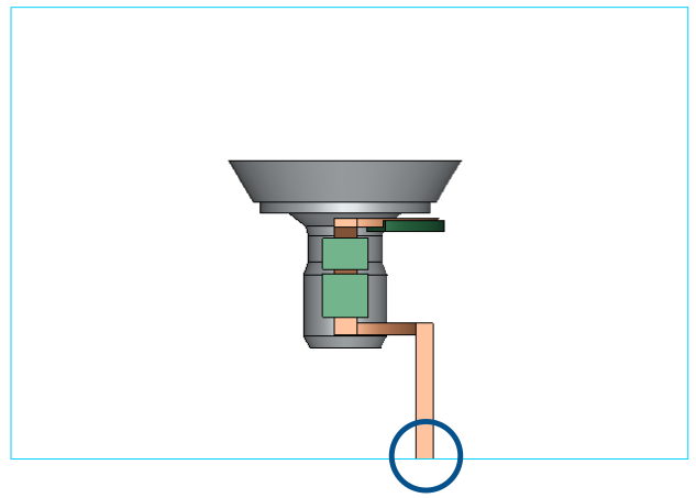
Terminal placement
If you are building a 3D simulation, remember that inductor terminals must always be on the same plane as one of the air box sides.
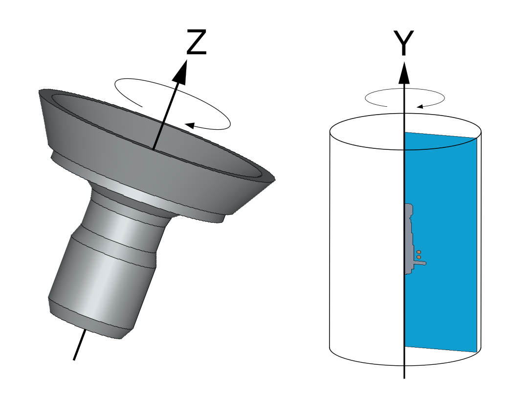
Rotation axis
If you are using Motion to define rotation for fully axial-symmetric workpiece, the rotation axis must be Z axis.
If you are creating an axial-symmetric 2D geometry, remember that symmetry axis must be Y axis.
Mesh
Tips for mesh are useful for those who want to start with Advanced Geometry Editor, as the rest of simulation screation approaches create mesh automatically.
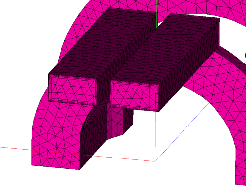
Skin layer
Always create proper resolution for the skin layer in inductor and workpiece, because without it in mesh the electromagnetic and thermal results of the simulation will be incorrect.
NOTE: Don’t get confused when you see Viscous layers function to resolve the skin layer – this is simply an analogical tool from Fluid dynamics which is used for mesh layer creation in our mesh editor.
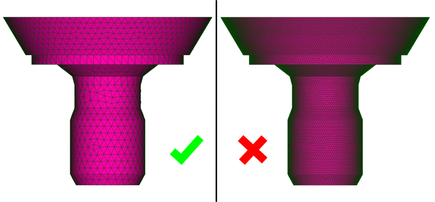
Mesh size
Pay close attention to the mesh size, especially for 3D simulations. If element count goes above 300 thousand elements, consider simplifying your simulation through geometry or symmetry, as simulations with large mesh will take much longer to calculate.
Physics
Amplitude current
Those who are calculating with current as their power input should remember that the current defined in CENOS is Amplitude, not RMS current.
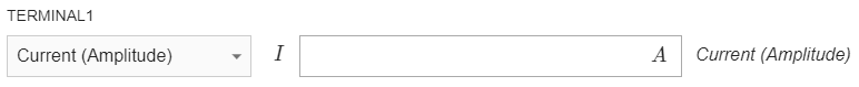
If you know the RMS value of the current flowing through your inductor, you should multiply it by square root of two before you enter it in CENOS.

Movement
If you want to simulate a movement which requires a moving mesh such as scanning or rotation of non axial-symmetric workpiece, it can only be defined through Advanced Geometry editor.

Symmetry in From CAD
If you are using From CAD approach to simulate symmetry cases such as slice, remember that automatic air box generation works only for full geometries, meaning that for symmetry cases you have to create and import air as CAD with the rest of your geometry.
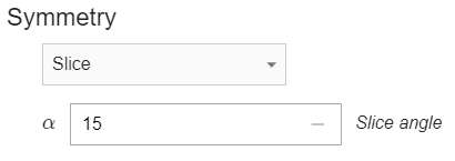
Symmetry definition
If you are calculating a symmetry case, don’t forget to change symmetry definition from Full 3D model to Slice and enter angle of your slice to calculate power and other parameters for the full system.