How to define scanning in CENOS
Heat treatment with induction heating method is a viable choice for not only heating of small mechanical parts such as gears, but also for heating and hardening of long parts such as metal strips or shafts of any kind.
CENOS platform offers a moving mesh to simulate induction heating of a workpiece moving through the inductor or scanning.
When to use scanning?
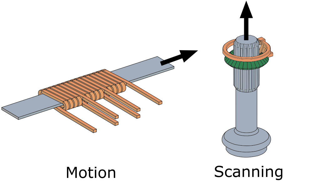
Scanning is used when the geometry moving through the inductor is too complex or cannot be simplified enough to use Motion, which requires an infinite, one profile workpiece to define linear movement.
In this example the strip heating can be simulated using Motion, because the workpiece can be defined as infinite, and it's profile does not change. The splined shaft is a finite part with different profiles across its height, which means that Motion will not work and Scanning must be used.
How to use scanning?
First you need to create a parametric geometry with a parameter that defines the inductor position along the workpiece longitudinal axis. Then you introduce the scanning in the CENOS interface by defining the starting value of the inductor position parameter and the scanning speed.
IMPORTANT: Scanning is implemented in the simulation through the inductor parametrization - the inductor will be the one to move along the workpiece.
1. Create a parametric model
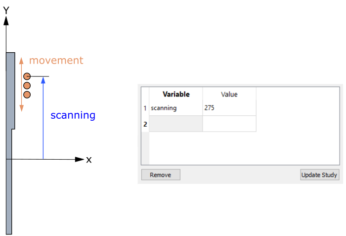
Create a geometry with a parameter that allows you to change the position of your inductor along the workpiece. In this 2D axial-symmetric example the Y coordinate was made parametric for the center point of the upper winding of the coil. Because the windings were created from this point, through it we can change the position of all windings together.
2. Define scanning parameters
When your geometry is ready and the mesh is exported to CENOS, you can define the scanning parameters. In SIMULATION CONTROL window check Enable box under Dynamic geometry variables. Define the start position of the inductor through Initial value and the inductor moving speed through Velocity.
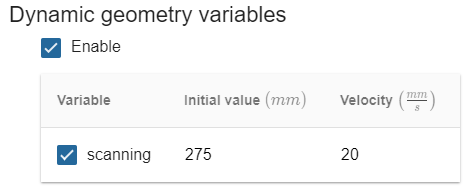
IMPORTANT: By changing the Velocity value from positive to negative you can change the direction of movement!
Limitations
To correctly use CENOS scanning feature, there are a couple of limitations and things to avoid.
Movement within computational domain
When defining the Initial value and Velocity, make sure that the start position of the inductor is within air domain, and that during heating time inductor does not move outside of the computational domain. In either case if the inductor leaves the computational domain, it will cause errors during computing and in result post-processing.
IMPORTANT: Make sure that the inductor does not leave the computational domain!
Meshing
When creating mesh for Scanning, there are 2 things to remember:
Do not use Extrusion 3D meshing algorithm - it will result in faults during re-meshing. Stick with the automatic meshing algorithms or NETGEN!
The number of different meshes in your Salome file should be as small as possible - the more meshes you have, the more time it will take to generate the mesh, because even though only one mesh is being used, they are all being generated, which takes time. Also the risk of calculation failure increases with the number of meshes, because one of them might be faulty, which can cause problems during scanning mesh generation.
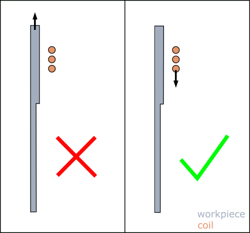
Workpiece movement
The scanning is defined through the inductor geometrical parameters, which allows it to move along the workpiece. As the velocity between the inductor and workpiece is relative, the workpiece could be moved as well, but it is not advisable, because the time to recalculate the mesh for every time step in the case of a moving workpiece will be far more longer that in the case of a moving inductor.
IMPORTANT: The scanning should be used to move only the inductor, not the workpiece.
Parameter count
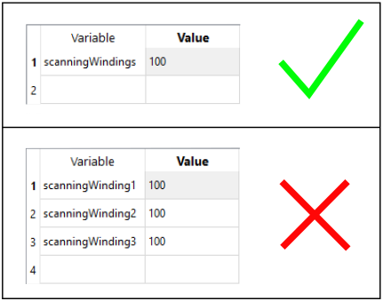
Because scanning uses Salome parameters, the count of parameters is important - whole inductor must be parametrized with one parameter.
IMPORTANT: You can only select one parameter for scanning, so be sure to parametrize inductor with only one parameter.