Stranded coil/Litz wire
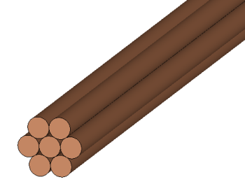
Many different coils and inductors are used in induction heating process, one of them being stranded coil. Stranded coil refers to a coil consisting of many fine turns of conducting wires.
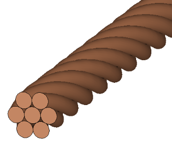
Electromagnetic analysis of a stranded coil can be complicated, because the geometry of the coil is complex. CENOS gives you the advantage to define a solid coil as stranded through a specific domain type, and ease the simulation of it to a minimum. CENOS allows you to define and simulate a specific stranded coil type, called Litz wire.
When to use Stranded Coil domain?
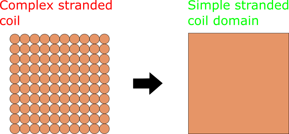
Stranded Coil domain type can be used in 2D and 3D simulations of stranded coils where the count of strands is too high to efficiently resolve them through geometry.
With Stranded Coil domain type definition you can not only decrease the mesh element count and calculation time of your simulation, but also ease the geometry creation process, as you can create a solid coil and define it as stranded, without the need to manually create each strand.
IMPORTANT: Simply replace the stranded coil with an equivalent size cross-section shape, define it as Stranded Coil Source and calculate!
How to use Stranded Coil?
You can easily access Stranded Coil Source domain under Domain type dropdown menu.
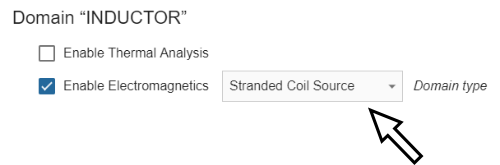
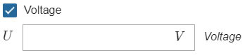
When Stranded Coil Source has been selected, Domain properties will appear, consisting of 4 parameters - Current (Amplitude) or Voltage (only for 2D), Number of turns, Fill Factor and Cross section area (specific to 3D definitions only).
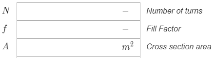
Number of turns, Fill Factor and Cross section area are stranded-specific parameters, which are used to define the geometrical distribution of strands over the solid inductor.
If you want to simulate Litz wire inductor, simply check the Litz wire check box.
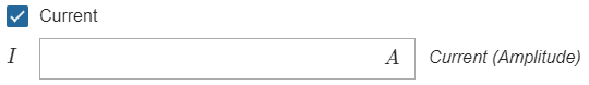
Current
Current definition depends on the stranded coil type you are using.
The current you define when using only Stranded Current Source domain type is current in one strand.
- Example: If you want to switch from a solid inductor with 1000 A current to a simple stranded coil with 10 strands and total current of 1000 A, then you need to enter 100 A in Current (Amplitude) box.

If you have checked the Litz wire check box, then the total current will be equal with the current in each strand, as the strands are connected together in the ends.
- Example: If you want to switch from a solid inductor with 1000 A current to a Litz wire with 10 strands and total current of 1000 A, then you need to enter 1000 A in Current (Amplitude) box.

Number of turns
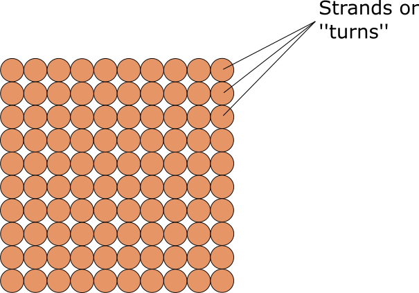
Each strand of a stranded coil is called a turn. With Number of turns you define how many strands your coil has.
Fill Factor/Cross section area
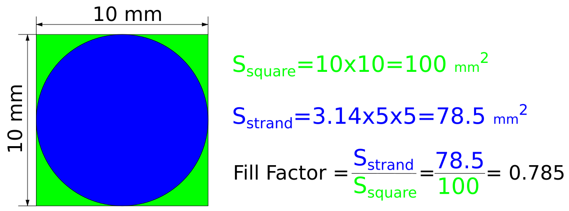
Fill Factor defines how much of the solid inductor area is occupied by strands.
Cross section area defines the total area occupied by strands.
For example, if you define a 10x10 mm square as Stranded Coil Source with 1 turn, the Fill factor and Cross section area could be calculated as follows:
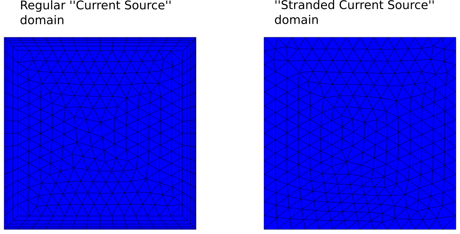
Mesh
Stranded Coil Source domain allows not only to simplify the geometry, but to save on element count as well. If you are using Stranded Coil Source domain, you don't need to resolute the skin layer which you would if you would use simple Current Source domain.
IMPROTANT: Make sure that the mesh in Stranded Coil Source domain is uniform!